Pactor für Einsteiger

 
a a
  Bitte beachten SieCopyright & Haftungsausschluss    
   

The HF-Transceiver Kennwood TS-50 has no special connector for the communication with the PTC.

The 4 needed pins are available on the mike-connector at the front-panel:

- AF from PTC to the TRX

- AF from TRX to the PTC

- PTT (push to talk) from the PTC to the TRX

- Ground

The use of these pins during normal SSB-operation is really inconvenient without a modification: You have to take off the mike-plug to access the PTC-pins.

The following picture-1 shows the pin-connections between TS-50 and PTC:

picture 1


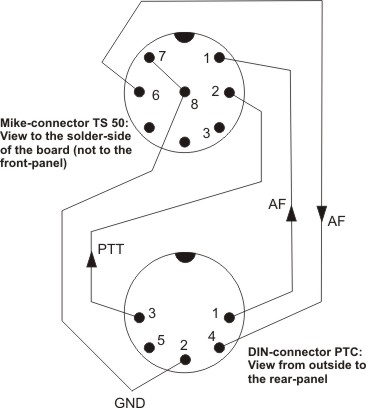
Make a connection-cable according to picture-1

- for the PTC-side with a 5-pin DIN- connector.

- for the TRX-side with 4 soldered wire-ends plus the twisted and soldered shield.

You can use a normal DIN-cable, if all pins are wired and shielded.

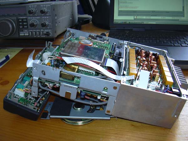
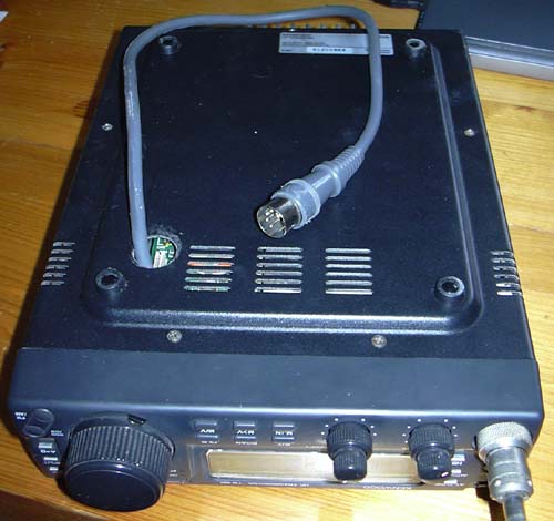
Take off the bottom-cover and the top-cover of the TS-50 case.

Take off the front-panel (4 screws)

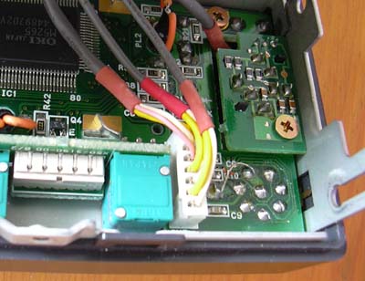
Carefully pull off the grey contact-band (left side of picture-2 rising into the air) from the socket on the TRX-side (not the front-panel-side)

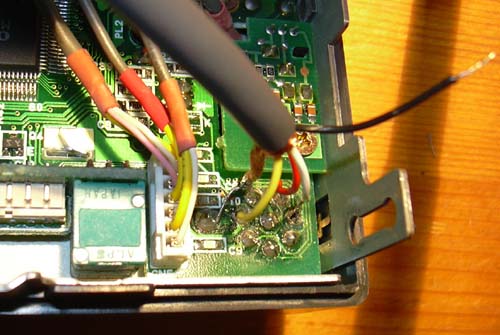
Put some bits under the body of the TS-50, so that the front-panel lies almost flat. Like that the mic-socket is best accessible (picture-3)

Now read first about the assembly

Solder 4 wires according to picture-1 and picture-4 to the mic-socket.
GND is the shield of the DIN-cable.

The wire from pin-5 of the DIN-connector ( power-supply for the PTC) will be connected to 12V inside the TS-50.
That is in the filter-unit at the fuse, which is used for the external tuner.

To do so open the cover of the filter-unit ( in picture-2 you can see the relays and the coils of the filter-unit)

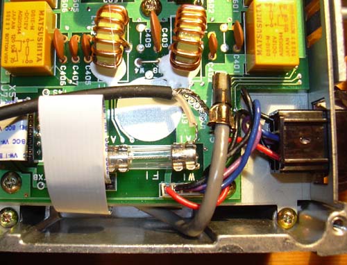
Solder one end of a "shielded wire" to side A1 of the fuse.

Solder the other end of the "shielded wire" to the wire, that comes from pin-5 of the DIN-connector (picture-4: black wire)

Solder the shield of the "shielded wire" to ground.
That is at the foot of the HF-connector next to the fuse.
(picture-5 between fuse and tuner-connector)
The shield at the other end of the "shielded wire" gets no connection.


picture-2 : TS-50 opened

picture-3: Mic-socket of the TS-50

picture-4: 3soldered wires and the shield. Black wire for power-supply.

picture-5: The black "shielded wire" for power-supply

picture-6: ready for connection to the PTC

Assembly
At the bottom of the TS-50 is a hole meant for the access to the serial-port. The hole is covered with tape.
The DIN-connector almost goes through that hole. Unfortunately only almost...
Open it a little with a tool (I don´t know the english word...)
Or better: Get the cable through the hole before soldering!

Carefully put the grey contact-band coming from the front-panel into its socket.
Helpful is a tool like that (cover it for protection with tape):

Be sure that the grey contact-band is fully in with 90 degrees to the socket. (the blue stripe on the grey contact-band should be parallel to the socket).
Assemble the front-panel with 4 screws.
Put the DIN-connector from the inside through the hole in the bottom-cover and assemble the cover.
The new DIN-cable can be aligned along the shielded box, even though the space is limited.

That´s all (picture-6). Don´t forget to adjust the audio-levels of the PTC!
If You understand german, have a look at "PACTOR für Einsteiger" on my website www.sy-kaya.de

vy 55, Rüdi DJ9UE

  zurück
Impressum   letzte Änderung : 10.10.2013 Copyright Rüdiger Hirche